Porting CHIP8 to an ESP32
I am really fascinated by how computers or a certain piece of electronic hardware work. Building emulators is an easy way to look under the veil of a piece of hardware or some processor using the software. Of course, it is not easy to develop an emulator for modern-day hardware as they are much more complex. One easy way to get started is to build an emulator for older hardware as processors used to be much simpler than what we have today in 2020. The best part is, some of the core concepts remain the same.
Building a CHIP8 “emulator” is one of the very popular ways of getting started with emulation programming. I put quotes around the emulator in the previous sentence because CHIP8 is a virtual machine. The CHIP8 programming language( sort of the “Byte code” ) is used to write programs that target the CHIP8 virtual machine. As the CHIP8 virtual machine has opcodes(operation code) that are similar to the modern processor instruction set and there is only a small number of them, building a CHIP8 emulator is one of the best ways to get started in the world of emulation.
I wrote a CHIP8 emulator using C++17 with SFML to handle IO(input/output) for desktop Linux. But this article is not about building a CHIP8 emulator for desktop. There are already a plethora of articles which does a much better job in explaining than what I could possibly do(article). I wanted a bit of extra challenge so I decided to port the existing CHIP8 emulator I wrote for the desktop to a smaller, resource-constrained microcontroller, ESP321. ESP32 is very cheap and it comes with a built-in Bluetooth Low Energy (BLE), which I will be using for giving inputs to my emulator.
I will not go through every single detail on how to build an ESP32 based CHIP8 emulator in this article. But this article will give you the overall picture plus some of the issues I faced while building the emulator that might come in handy for someone deciding to build their own. This might be a fun project for someone who already has some basic experience with embedded systems and looking to improve their skills with more advanced topics such as BLE, RTOS, filesystems (FS), etc.
Let’s get rolling!
Prerequisites
Hardware
- ESP32 DevKitC (or any other varieties of ESP32 dev board)
- ILI9341 based 2.4 inch 240x320 SPI TFT (link)
- Bread board
- Jumper wires
- Android phone (Will be using an (Android App) as the Keyboard to interact with ESP32)
Software
C++17 with the native ESP-IDF (based on FreeRTOS) framework is used to program the ESP32. It was definitely nice to use modern C++ to write the firmware. I decided not to use Arduino. Arduino is great to get started and to quickly prototype something, but probably not great if you want to learn what is going on underneath and have total control due to its abstraction model. The best way to learn embedded software is to create your own abstraction with the native SDK provided by the vendor.
Bluetooth Low Energy(BLE) is used to communicate with the ESP32. ESP-IDF comes with a bluedroid based Bluetooth stack. The display driver for ILI9341 is based on this repo. I made a fork of it because I had to adapt the code a bit. It is added as a submodule in my main repo.
Optional
I used the Flutter SDK to develop the Android app. This is totally optional. You can use the android app I made to control the ESP32-CHIP8. It was a lot of fun developing the android app as I have never developed one before. And, especially, it is really easy to quickly prototype something with Flutter.
Implementation
 |
|---|
| Class diagram of the ESP32 CHIP8 system |
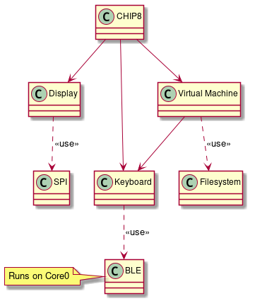
The class diagram shown above roughly indicates different components and how they are related. The CHIP8 class in the diagram is sort of an orchestrator that glues different components together.
In the following subsections, we will discuss each class more in-depth. I have split the following subsections into Concept and Porting. The Concept part will mainly give the reader a bit of background on what I am trying to achieve, and it applies to any platform. In the Porting part, ESP32 specific changes that were needed to be incorporated is discussed.
Virtual Machine (VM)
Concept
The VM class implements the core logic of the CHIP8 VM in our system such as evaluating OPCODES and taking the necessary action. The CHIP8 has 4KB RAM and 16 8-bit general-purpose registers. The registers and RAM are emulated by using std::array. The main job of a VM can be summarized as follows:
 |
|---|
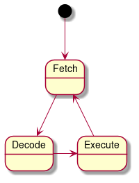
| Virtual Machine’s state diagram |
The fetch part retrieves the OPCODE from the RAM based on the current Program Counter. The decode part looks for the current OPCODE implementation, which in our case is a simple switch statement. The execute part just executes the implementation corresponding to that OPCODE.
Porting
It was a bit surprising but I almost had no issues with this part when I ported from desktop to ESP32. But in a way, it makes sense because the idea of having a VM is to have the portability across multiple platforms. I did have to change the debug print statements from using fmt in desktop to ESP_LOG functions for ESP32. But it was a very minor change.
The main takeaway is to not introduce platform-specific dependency such as access to the display, keyboard in this class for easy portability.
Filesystem
Concept
The CHIP8 ROM contains the OPCODES in binary format and it needs to be stored in a place where the VM can access it. In Linux (or any other big operating OS) it is pretty easy to store the ROM in a folder. But ESP32 microcontroller has a Real-time operating system (FreeRTOS in this case) which is not a full-blown operating system.
Porting
ESP32 supports SPIFFS, which is a file system for SPI NOR flash devices for embedded systems. SPIFFS could be used as a filesystem to load the ROM into the VM.
ESP32 has a partition table for its flash memory. It can be found in the partitions.csv file, usually present in the root folder of the project. The SPIFFS storage details should be filled in the partitions.csv file. The csv file in my project looks as follows:
# Name,   Type, SubType, Offset,  Size, Flags
nvs,      data, nvs,     ,        0x6000,
phy_init, data, phy,     ,        0x1000,
factory,  app,  factory, ,        2M,
storage,  data,  spiffs, ,        1M,
As seen from the csv table, the last entry is reserved for data storage that has a capacity of 1 Megabyte (more than sufficient for a CHIP8 ROM).
Now that the flash space is reserved for storage, the ROM needs to be written to that memory space.
ESP32 provides a convenience function: spiffs_create_partition_image in CMake to convert a particular folder into binary in correct data format, and also allows to be written onto ESP32 flash along with uploading(“flashing”) your code. So a folder needs to be created for the ROMs and can be easily used in our program in ESP32 using SPIFFS. This is the code I added in CMakeLists.txt file:
if(FLASH_SPIFFS)
    message("Flashing rom along with the app")
    spiffs_create_partition_image(storage ../../externals/rom FLASH_IN_PROJECT)
else()
    spiffs_create_partition_image(storage ../../externals/rom)
endif()
Enabling the FLASH_SPIFFS option while building the project will allow uploading both the application and the ROMs onto ESP32.
By doing all this, the ROM file can be easily accessed in the program similar to how it is done in Linux as follows:
...
std::ifstream file;
file.open("/spiffs/test_rom.ch8", std::ios::binary | std::ios::ate);
Keyboard
Concept
The original CHIP8 keyboard had a 16-key hexadecimal keypad to interact with the console. The keyboard layout is shown below:
 |
|---|
| CHIP8 Keyboard layout (Image courtesy: link) |
In CHIP8 there is no concept of interrupts. So CHIP8 VM manually polls for a keypress when it needs to receive an input.
Porting
In the desktop implementation, I used SFML library to get the key that is pressed on the keyboard. But for ESP32, I decided to use Bluetooth Low Energy (more on this in the next section) as a way to give keyboard inputs. The Keyboard object runs in core 1 and the BLE object runs in core 0 of ESP32 and is created as part of different FreeRTOS tasks. So the easiest way to pass a message between two tasks is using the FreeRTOS Queue. The BLE class puts the value it receives via bluetooth on to a queue using xQueueSend function and the Keyboard class receives the value using xQueueReceive function.
BLE
As indicated in the previous Keyboard subsection, BLE is used to give inputs to the ESP32-CHIP8 system. ESP32 will run a BLE GATT(Generic Attribute Profile) server. In BLE terms, ESP32 will act as a peripheral that advertises itself to be connected to a central (our smartphone in this case).
Making BLE work took me the most time in this complete project as I had zero experience with it before and I didn’t want to use any third-party library for it. There is a third-party library by Neil Kolban if you don’t want to write your own GATT server. But in case you are starting the BLE journey from scratch like me, writing a simple GATT server would be a nice way to understand some basics about it. The following are some of the articles/videos that helped me in learning the basics about BLE:
- ESP32 gatt server example
- Introuction to Bluetooth Low Energy
- All about ESP32 - BLE basics
- Introduction to BLE with Nordic semiconductors
- Blob is a good word (Embedded.fm podcast)
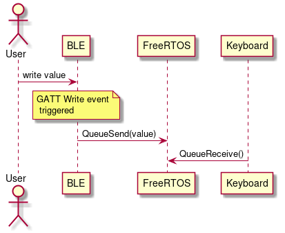
The important thing about the BLE stack is that everything works on callbacks. This is something that took me some time to wrap my head around. So, whenever a central(computer or a smartphone in this case) writes to the peripheral(ESP32), a callback is called with a write event that contains the value that was written. As ESP32 has two cores and has an RTOS, these asynchronous events are gracefully handled. So whenever a value is written to the ESP32 BLE server, the BLE class object will push that value to a FreeRTOS queue that will be used by the Keyboard class later. A simple sequence diagram of that flow is shown below:
 |
|---|
| BLE and Keyboard class sequence diagram |
Display
Concept
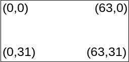
The original CHIP8 machine uses a 64x32 pixel display in this format:
 |
|---|
| Chip8 display layout (64 * 32 pixels) |
A simple method to store the pixel map of the display is to have an array (std::bitset if you want to have a lower memory footprint) of length 2048( 64 * 32). Only two instructions(DRW and CLS) in CHIP8 VM modifies the display pixels. One easy optimization would be to draw on the display only if either of the two instruction was executed in that cycle. By doing this small optimization, we avoid the expensive draw on the display operation when it is not needed. I used this optimization even in my desktop version of my CHIP8.
Porting
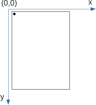
I am using a 2.4 inch 240x320 SPI TFT for display based on the ILI9341 driver. The first problem to tackle is the default orientation of the TFT display. The picture below depicts what happens if a pixel is set at (0,0):
 |
|---|
| Pixel (0,0) set in TFT display |
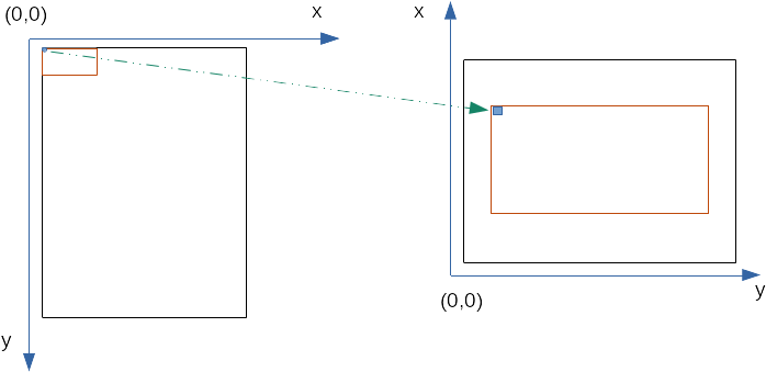
When we want to play, the display should be in landscape mode rather than portrait mode. So we need to perform a transformation from the default orientation of the TFT display to the actual CHIP8 display orientation. And as CHIP8 uses only 64 * 32 display pixels, we can scale it in our physical TFT display as the available display pixel is 240 * 320.
We can scale the CHIP8 pixel map by 4 times in our physical TFT display (64 * 4 = 256 & 32 * 4 = 128). And the way we scale up by 4 times is very simple: each pixel in the CHIP8 pixel map will correspond to a square of width 4 in the physical display. The transformation we want to achieve is as follows:
 |
|---|
| Left: Untransformed and unscaled projection of CHIP8 display pixel map on physical TFT display Right: Transformed and scaled projection of CHIP8 display pixel map on physical TFT display |
So as shown in the figure above, we need to do two things:
- Transform the CHIP8 pixel coordinates to the TFT display coordinates in landscape mode
- Scale each CHIP8 pixel into a square of scale width in the TFT display.
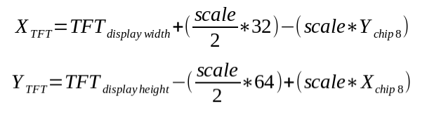
Using simple coordinate geometry, we can make the transformation as follows:
 |
|---|
| Transformation equation from CHIP8 pixel map to the actual TFT display orientation |
XCHIP8 and YCHIP8 is the CHIP8 VM coordinates of a pixel. XTFT and YTFT is the coordinates of our TFT display that we need to send SPI commands to display the pixel.
All righty! Let’s now try out in real hardware how our transformation looks so far.
 |
|---|
| Output in the TFT display on test rom |
Hurray! The transformation is a success, but the display output is terribly slow. In my desktop implementation, this test rom would take less than a second, and with my esp32, it is taking almost 20 seconds! I expected my ESP32 CHIP8 to be slightly slower than my desktop, but not this slow. It is time for some more optimization!!
As I mentioned before, we need to draw the graphics on the TFT display only for two instructions:DRW and CLS. In my naive implementation, whenever I get an instruction to draw, I redraw the complete CHIP8 pixel map onto the screen. This means at least 2048 SPI transactions are happening to the screen when a draw instruction is received. But if only some pixels are changing in a cycle, instead we could update only the pixels that have changed from the previous frame. Luckily with the 512 kB RAM, caching could be used to improve the performance.
The caching that is used here is pretty straightforward. I have a local cache of the previous frame using std::bitset (Using bitset here is memory efficient. It takes only 256 bytes to store the information of 2048 pixels). Whenever a draw instruction is received from the VM, only the pixels that have changed from the previous frame are drawn. Pseudocode might look something like this:
void drawGfx()
{
    for (auto [x, y] : chip8_display_coordinates) {
        // First transform the coordinates to TFT display coordinates
         auto [new_x, new_y] = transformCoordinates(x,y);
        // Check if the pixels have changed in the new frame
        if (chip_display_pixels(x,y) ^ disp_cache(x,y)) {
         // Update the cache
         disp_cache(x,y) = chip_display_pixels(x,y);
         //Draw the pixel on the display
         TFT_draw(new_x,new_y);
        }
    }
}
Now that the caching is applied, let’s see the improvement in the performance:
 |
|---|
| Output in the TFT display with caching to improve perf on test rom |
Perfect! It takes less than a second similar to the desktop implementation. That is more than a 10x improvement in performance compared to my naive implementation.
CHIP8 (class)
Concept
As seen in the SW Class Diagram, this CHIP8 class initiates and ties everything together. The main responsibility of the CHIP8 class is to initialize all the classes and orchestrate coordination between them to run the CHIP8 VM.
Porting
 |
|---|
| Sequence diagram of the CHIP8 class interaction with other classes |
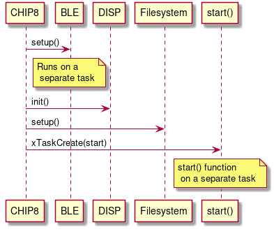
First, the CHIP8 class spawns a BLE task with an appropriate service to process the incoming request. It is done by calling a few member functions of the BLE class. Then the CHIP8 class initializes the TFT display and the SPIFFS filesystem. And finally, it spawns a new task with a function that is indicated as start() for running the emulator itself (To create a new task, a function needs to be provided to the FreeRTOS task create function). Running the emulator as a part of a separate task allows specifying the stack size and the core it needs to run (Core 1 was chosen here as BLE runs on Core 0)
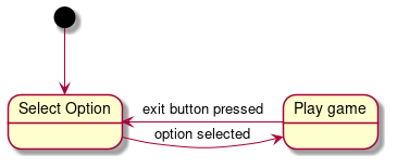
The start function is implemented as a simple state machine as follows:
 |
|---|
| State diagram of the start function |
The new task created waits for an option to be selected, and once the new option is selected, the game starts by loading the correct CHIP8 ROM into the virtual machine. There is also an exit button observer (aka Observer Pattern) to exit the game and go back to Select Option state when the user wants to play a different game.
A short video snippet of the completed project:
 |
|---|
| A short video snippet of the final working ESP32-CHIP8 with CHIP8 numpad app |
Conclusion
This work hits the perfect sweet spot as a side project in terms of difficulty and learning opportunities. Of course, I have mentioned only the happy flow here, but trust me, there were several moments I doubted myself as an embedded software engineer during the project. Moments like these reassure me that I am learning something new.
Doing a CHIP8 emulator in an operating system like Linux is also a good learning experience and a nice introduction to the world of emulation. But things that are trivial in Linux was not so anymore when I started porting them to a microcontroller. The caching I described in the Display subsection is one such example where I didn’t have to do such optimization in Linux but I had to do it in ESP32. That is why I feel it is a very good project for someone who has already played around with Arduino and wants to go beyond their comfort zone.
The complete ESP32 source code can be found here and the Android app can be found here. Feel free to have a look at it and also report if you find something weird.
Hope you enjoyed the article. Happy coding!
1 Some hardcore embedded folks might say ESP32 is not really resource-constrained because of its 512 kB RAM and 4 MB flash, but compared to my laptop, an ESP32 is definitely resource-constrained.